


Hydraulic Hose Failure Causes and a Practical Troubleshooting Process
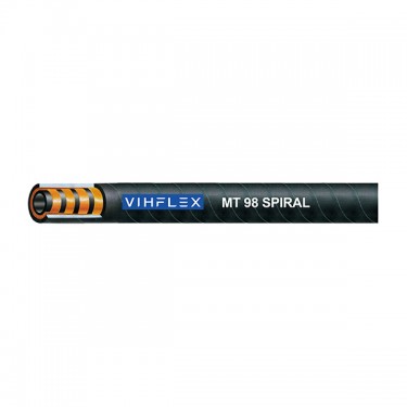 A hydraulic hose can fail because of external abrasion, incorrect routing, excessive heat, pressure spikes, fluid incompatibility, fitting problems or installation errors. In many cases, the visible damage is only the final symptom. A hose that bursts, leaks or wears through may have been exposed to a system condition that will also damage the replacement assembly unless the root cause is corrected.
For maintenance teams, the purpose of hydraulic hose troubleshooting is not simply to remove and replace a failed line. The more useful process is to identify where the damage occurred, review the operating condition, inspect the installation path and confirm whether the hose-and-fitting assembly matches the actual duty. This approach is relevant for mobile equipment, construction machinery, agricultural machinery, mining equipment, presses and industrial hydraulic systems.
Before inspection, isolate the equipment, release hydraulic pressure according to the equipment procedure and allow hot components and fluids to cool. Never use a hand or other body part to locate a pressurized hydraulic leak. High-pressure fluid injection can cause serious injury and requires immediate medical attention.
Start with the Failure Pattern, Not the Replacement Part
The location and appearance of a failed assembly provide useful diagnostic information. A leak at the fitting may indicate a sealing, thread, crimping or fitting-orientation issue. Cover damage at a repeated contact point may indicate abrasion caused by routing or clamp movement. A burst away from the fitting may require a review of pressure peaks, hose condition, temperature, fluid compatibility or reinforcement selection.
Before removing the failed hose, record the equipment location, the function of the line, the hose marking, the fitting type, the approximate assembly length and the visible damage pattern. Where practical, take photographs of the hose in its installed position. This information is especially useful when the replacement must match a specific hose construction, routing path or fitting orientation.
Information to Record During Inspection
- Equipment type, system location and function of the hydraulic line
- Visible hose marking, standard reference, size and part identification
- Hose length, fitting type, fitting angle and fitting orientation
- Leak location, burst location or area of abnormal wear
- Condition of the outer cover, reinforcement, fittings and protective guards
- Potential contact points with machine structures, clamps, edges or moving components
- Operating temperature, fluid type and any recent change in duty cycle
- Recent repairs, fitting replacements, routing changes or component modifications
Common Hydraulic Hose Failure Causes and Visible Symptoms
External Abrasion and Cover Wear
Abrasion occurs when the hose cover repeatedly contacts a machine frame, another hose, a clamp, a sharp edge or a moving component. The outer cover may first appear polished, flattened, cut or rubbed through. Continued wear can expose the reinforcement layer, which should be treated as a replacement condition because the hose structure may no longer provide the required protection and performance.
The corrective action is not limited to replacing the damaged hose. Review the routing path, hose length, clamp position, movement range and nearby contact surfaces. A protective sleeve or guard may help where abrasion cannot be eliminated by routing, but it should not be used as a substitute for correcting a severe pinch point, sharp edge or excessive hose movement.
Hose Twisting and Reinforcement Stress
Twisting can occur during assembly installation when the hose is rotated with the fitting, when fitting orientation is not checked before crimping, or when machine movement transfers torque into the hose. Visible spiral cover marks, distorted hose lay lines, uneven bending or repeated fitting-area damage can indicate torsional stress.
A replacement assembly should be installed without forcing the hose into position. For assemblies with angled fittings, confirm the required orientation before installation and verify that the hose can move through the equipment range without twisting. If the same location repeatedly shows twist-related damage, review both fitting orientation and the hose routing path.
Excessive Bend Radius and Kinking
A hose installed below its recommended bend radius may kink, flatten or experience localized stress near the fitting. This condition can restrict flow, increase heat generation and shorten service life. Tight routing around machine structures, incorrect hose length and unsupported motion are common causes.
Check the installed hose in all operating positions, not only when the machine is stationary. A line that appears acceptable at rest may become stretched, kinked or crushed when an excavator boom moves, a cylinder extends or a mobile machine articulates. The replacement assembly may require a different length, fitting angle, routing path or hose construction suitable for compact equipment layouts.
Heat Exposure and Thermal Degradation
High ambient temperature, hot hydraulic fluid, nearby exhaust systems, engine components or insufficient system cooling can degrade rubber materials over time. Signs may include hardening, cracking, softening, discoloration, blistering or an unusually brittle cover. Heat can also accelerate aging of the inner tube and reinforcement interfaces, even if the outer cover does not initially show severe damage.
When heat-related damage is suspected, inspect the complete hydraulic circuit. Confirm fluid temperature, cooling performance, hose routing near heat sources and whether the hose construction is suitable for the operating environment. Replacing the hose without addressing excessive temperature may lead to recurring failure.
Fluid Incompatibility and Inner-Tube Deterioration
The inner tube must be compatible with the hydraulic fluid and any cleaning fluid, lubricant or process medium that may enter the line. Incompatibility can contribute to softening, swelling, cracking, loss of adhesion or contamination in the system. Changes in fluid type, additive package or operating temperature should therefore be reviewed when a hose fails without an obvious external cause.
Where possible, inspect the removed assembly for evidence of internal deterioration and review maintenance records for recent fluid changes. The correct replacement decision should consider the actual medium, temperature range and duty cycle, not only the nominal pressure rating.
Pressure Spikes and Impulse Fatigue
A hydraulic system can experience short-duration pressure peaks that exceed the normal operating pressure. Repeated pressure impulses can fatigue a hose assembly over time, particularly in demanding equipment with rapid cycling, frequent load changes or severe operating conditions. A burst may occur after repeated stress even when the average system pressure appears to be within the expected range.
Review the circuit design, relief-valve performance, actuator motion, pressure records and duty cycle when impulse-related failure is suspected. The replacement hose should be selected according to the actual application requirement, including pressure peaks and impulse conditions. For higher-pressure or high-impulse systems, the hose construction may need to be reviewed rather than simply matching the previous assembly by size.
Incorrect Fitting Selection or Assembly Problems
Leaks near the fitting can result from mismatched thread forms, damaged sealing surfaces, incorrect fitting selection, improper fitting orientation, loose connections, corrosion, insufficient crimping control or use of an incompatible hose-and-fitting combination. A fitting that appears similar may not share the same sealing method, thread specification or dimensional requirement.
When replacing a failed assembly, identify the fitting by its full connection type rather than by visual appearance alone. Thread standard, sealing surface, hose bore, fitting series, material and fitting angle should all be checked. The hose fitting and coupling category includes multiple metric connection options and other configurations, so the assembly requirement should be confirmed against the existing component or technical drawing. Review hose fitting and coupling configurations before finalizing an assembly specification.
Contamination, Corrosion and Environmental Exposure
External contamination can conceal early warning signs such as wet fittings, cracked covers and abrasion points. Corrosion at fittings or metal components can affect the connection area, especially in outdoor, marine, chemical or high-humidity environments. Dirt and debris trapped under protective sleeves or clamps can also create localized abrasion.
During scheduled maintenance, clean enough of the assembly to inspect the hose cover, fitting transition, clamp position and contact areas. Do not treat a dirty or oily exterior as normal without determining whether the fluid originates from the hose assembly, a nearby component or a separate system leak.
Hydraulic Hose Failure Symptom and Corrective Action Table
| Visible Symptom | Possible Cause | Inspection Focus | Typical Corrective Action |
|---|---|---|---|
| Outer cover rubbed smooth, cut or worn through | Repeated contact with metal, another hose, clamp or moving part | Routing, clamps, machine movement and nearby contact points | Replace the hose and correct the routing or protection method |
| Steel reinforcement visible | Severe abrasion or cover damage | Extent of abrasion and source of contact | Remove from service and replace; eliminate the contact condition |
| Leak at fitting connection | Sealing, thread, fitting, torque or assembly issue | Thread type, seal condition, fitting series and connection surface | Confirm fitting compatibility and replace damaged components |
| Hose burst away from fitting | Pressure spike, impulse fatigue, heat, aging or internal damage | Pressure history, duty cycle, temperature and hose condition | Review system conditions and replacement hose construction |
| Hose failure near fitting | Excessive bend, fitting orientation, strain or crimping issue | Bend radius, hose length, fitting angle and installation path | Correct assembly geometry and avoid side-loading the fitting area |
| Cover appears cracked, hard or brittle | Heat exposure, aging, ozone or environmental degradation | Temperature, heat source proximity and storage conditions | Replace hose and evaluate thermal or environmental exposure |
| Hose feels soft, swollen or blistered | Fluid incompatibility, internal deterioration or heat | Fluid type, temperature history and internal hose condition | Review fluid compatibility and replace the affected assembly |
| Hose is flattened, kinked or restricted | Insufficient bend radius, incorrect length or clamp position | Dynamic equipment movement and routing at all operating positions | Revise routing, length or fitting angle before replacement |
| Spiral marks or twisted appearance | Torsion introduced during installation or machine movement | Fitting orientation and hose rotation during operation | Install without twist and confirm correct orientation |
| Repeated failure at the same machine location | Unresolved root cause in routing, pressure, heat or connection design | Previous replacement history and full system operating conditions | Conduct a complete application review instead of repeating the same replacement |
A Step-by-Step Hydraulic Hose Troubleshooting Process
Step 1: Make the Equipment Safe for Inspection
Follow the equipment lockout and pressure-release procedure before touching the hydraulic line. Support suspended loads, stop the power source where required and confirm that residual pressure has been relieved. If the system has recently operated at elevated temperature, allow components and fluid to cool before inspection.
Step 2: Inspect the Failed Assembly in Its Installed Position
Observe the hose before removal. Note whether it is stretched, compressed, twisted, rubbing against another surface or bent sharply at the fitting. Check clamps, guides, protective sleeves and nearby metal edges. If the damage is visible only after the hose has been removed, important routing evidence may be lost.
Step 3: Identify the Failure Location and Damage Pattern
Determine whether the problem is located at the fitting, in the hose body, at a bend point, near a clamp or at a repeated contact area. Compare the visible symptom with the likely causes in the table above. More than one factor may be present. For example, external abrasion may occur because a hose is too long, while the excessive length may also introduce twisting or kinking.
Step 4: Review Operating Conditions
Confirm the normal and peak pressure, fluid type, operating temperature, flow demand, duty cycle and environmental exposure. Ask whether the equipment has recently been modified, whether the fluid has changed and whether the machine performs a high-cycle or high-shock function. A replacement hose should be chosen according to the actual conditions of the circuit, not only the specification of the removed part.
Step 5: Confirm Hose, Fitting and Routing Compatibility
Review the required hose inside diameter, pressure capability, reinforcement construction, bend requirement and fitting connection. If the installation space is limited or the hose must flex repeatedly, routing and fitting angle may be as important as pressure rating. For a review of braided, compact and spiral options across SAE and EN series, see the hydraulic hose product range for different operating conditions.
Step 6: Install the Corrected Assembly and Reinspect
After the replacement assembly is installed, confirm that it is not twisted, stretched, pinched or in contact with an abrasive surface. Check the line through the complete range of equipment motion. After the system is returned to service, inspect for leaks and verify that clamps, guides and protective components remain in their intended positions.
Hydraulic Hose Troubleshooting Flowchart
Visible leak, burst, abrasion or deformation
                |
                v
Make equipment safe and release hydraulic pressure
                |
                v
Inspect hose in installed position before removal
                |
                v
Identify failure location:
Fitting area / hose body / bend point / contact point
                |
                v
Review visible damage pattern:
Leak / abrasion / twist / kink / crack / blister / burst
                |
                v
Check operating conditions:
Pressure peaks / temperature / fluid / duty cycle / environment
                |
                v
Check installation conditions:
Routing / bend radius / clamps / fitting orientation / contact points
                |
                v
Confirm corrected hose-and-fitting assembly requirement
                |
                v
Install, test for leakage and inspect through full machine movement
How to Reduce Repeat Failures in Mobile and Industrial Equipment
Review Routing During Full Equipment Movement
A hose route should be assessed during the actual operating range of the machine. This is especially important for boom, arm, steering, lifting, tilting and articulation functions. A line may be safe when parked but overstretched or crushed when the machine reaches a working position. Check dynamic movement after any repair that changes cylinder position, bracket placement, hose length or fitting orientation.
Use Clamps, Guards and Sleeves for a Defined Purpose
Clamps should stabilize the assembly without crushing it or forcing an unnatural bend. Guards and sleeves can provide added protection from external abrasion or heat where appropriate, but they do not correct an assembly that is fundamentally too short, too long, improperly routed or exposed to a sharp edge.
Match the Replacement Assembly to the Actual System Duty
A repeated failure may indicate that the original assembly was not appropriate for the real operating condition, or that the operating condition has changed. Review pressure peaks, temperature, fluid, routing and fitting requirements before selecting a replacement. This is particularly relevant for high-cycle machinery, heavy-duty hydraulic circuits and equipment operating in abrasive, high-temperature or outdoor environments.
Maintain Inspection and Replacement Records
Record the hose location, visible condition, replacement date, reason for replacement and corrective action. Over time, these records can reveal repeat failure patterns at a specific machine location or during a particular operating cycle. This information helps maintenance teams distinguish an isolated damaged assembly from a system-level issue.
Example: Diagnosing Repeated Cover Abrasion on an Excavator Boom Line
Consider an excavator boom line that repeatedly develops cover wear at the same location. A basic replacement may restore the machine temporarily, but the underlying condition can remain. During inspection, the maintenance team should observe the line throughout boom movement, identify whether the hose contacts a bracket or adjacent hose, check whether the clamp permits excessive movement and confirm that the assembly length does not create slack at one end of the travel range.
If the hose contacts a fixed structure only when the boom is extended, the corrective action may include revising the routing path, changing clamp placement, adjusting hose length or adding protection at a controlled contact point. If the hose is also twisted during movement, fitting orientation should be reviewed before the next assembly is installed. The goal is to remove the source of repeated abrasion rather than treating the cover damage as an isolated problem.
When to Review Hose Construction and Assembly Requirements
A technical review is appropriate when an assembly experiences recurring failure, when operating conditions are uncertain or when a machine modification changes the original routing or pressure demand. The review should include hose standard, inside diameter, pressure requirement, reinforcement type, fluid compatibility, temperature range, bend requirement, fitting configuration and installation path.
The product category includes braided, compact and spiral hydraulic hose options across common SAE and EN series, as well as selected application-specific products. Product selection should be based on the documented equipment requirement and actual system conditions rather than on the appearance of the previous hose alone. Compare hydraulic hose constructions for pressure and routing requirements.
Hydraulic Hose Manufacturing Background
Qingdao VIH Hose Co., Ltd is a hydraulic hose China manufacturer established in 2012, supplying braided, spiral and application-specific hose products for industrial and mobile hydraulic systems. The company reports an annual hydraulic hose production capacity of 20,000,000 meters, with 7 spiral production lines, 24 braiding production lines and hose production sizes from 3/16 inch to 4 inches.
For product and assembly evaluation, Qingdao VIH Hose Co., Ltd operates testing equipment for dynamic impulse testing, burst pressure testing, rubber tensile testing and ozone aging testing. The company also reports test capability related to flame retardancy, anti-static performance and wear resistance where required by the application. Hydraulic hose fittings and couplings are available for projects requiring compatible hose assemblies, including connection solutions for metric, American, British and Japanese system requirements.
FAQ
What is the most common cause of hydraulic hose failure?
External abrasion, incorrect routing, heat exposure, pressure spikes, hose twisting and fitting-related issues are common causes. The most frequent cause varies by equipment type and installation condition. A proper inspection should identify the visible symptom and the operating or installation condition that created it.
Why does a hydraulic hose fail near the fitting?
Failure near the fitting can result from excessive bend stress, incorrect fitting orientation, side-loading, hose twisting, poor routing, crimping problems or a mismatched fitting connection. Inspect the bend radius and routing immediately behind the fitting, as well as the thread type and sealing condition.
Can I replace a failed hose with the same size and type?
Not always. If the failure resulted from abrasion, routing, heat, pressure peaks, fluid incompatibility or fitting mismatch, replacing the hose with the same assembly may repeat the problem. Confirm the root cause before deciding whether the original hose construction, length, fitting angle or routing is appropriate.
How can hydraulic hose twisting be identified?
Possible signs include spiral marks on the cover, a visibly rotated hose lay, uneven bending, repeated stress near a fitting or a hose that changes position as the equipment moves. The hose should be inspected throughout the full range of machine movement, not only in a parked position.
Should a hose with exposed wire reinforcement be replaced?
Yes. Exposed reinforcement indicates significant cover damage and can leave the hose vulnerable to corrosion, abrasion and structural deterioration. The damaged assembly should be removed from service, and the source of abrasion or external damage should be corrected before replacement.
What should be checked when replacing a hydraulic hose assembly?
Check the hose standard, size, pressure requirement, fluid compatibility, temperature condition, assembly length, bend radius, fitting type, thread standard, fitting angle, routing path and clamp positions. Also confirm that the replacement will not twist, stretch, kink or rub against adjacent components during operation.
Related Hydraulic System Resources
Hydraulic hose failures are often linked to installation, routing, fitting compatibility or operating conditions. For a broader review of hose constructions and available SAE and EN product options, see the hydraulic hose category. When the inspection indicates a connection or interface issue, review the available hose fittings and couplings before specifying a replacement assembly.


